Installing Using Anaconda
This chapter provides step-by-step instructions for installing Fedora using the Anaconda installer. The bulk of this chapter describes installation using the graphical user interface. A text mode is also available for systems with no graphical display, but this mode is limited in certain aspects (for example, custom partitioning is not possible in text mode).
If your system does not have the ability to use the graphical mode, you can:
-
Use Kickstart to automate the installation as described in Automating the Installation with Kickstart
-
Perform the graphical installation remotely by connecting to the installation system from another computer with a graphical display using the VNC (Virtual Network Computing) protocol - see Installing Using VNC
Introduction to Anaconda
The Fedora installer, Anaconda, is different from most other operating system installation programs due to its parallel nature. Most installers follow a fixed path: you must choose your language first, then you configure network, then installation type, then partitioning, etc. There is usually only one way to proceed at any given time.
In Anaconda you are only required to select your language and locale first, and then you are presented with a central screen, where you can configure most aspects of the installation in any order you like. This does not apply to all parts of the installation process, however - for example, when installing from a network location, you must configure the network before you can select which packages to install.
Some screens will be automatically configured depending on your hardware and the type of media you used to start the installation. You can still change the detected settings in any screen. Screens which have not been automatically configured, and therefore require your attention before you begin the installation, are marked by an exclamation mark. You cannot start the actual installation process before you finish configuring these settings.
Additional differences appear in certain screens; notably the custom partitioning process is very different from other Linux distributions. These differences are described in each screen’s subsection.
Consoles and Logging During the Installation
The following sections describe how to access logs and an interactive shell during the installation. This is useful when troubleshooting problems, but should not be necessary in most cases.
Accessing Consoles
The Fedora installer uses the tmux terminal multiplexer to display and control several windows you can use in addition to the main interface. Each of these windows serves a different purpose - they display several different logs, which can be used to troubleshoot any issues during the installation, and one of the windows provides an interactive shell prompt with root privileges, unless this prompt was specifically disabled using a boot option or a Kickstart command.
|
In general, there is no reason to leave the default graphical installation environment unless you need to diagnose an installation problem. |
The terminal multiplexer is running in virtual console 1. To switch from the actual installation environment to tmux, press Ctrl+Alt+F1. To go back to the main installation interface which runs in virtual console 6, press Ctrl+Alt+F6.
|
If you choose text mode installation, you will start in virtual console 1 (tmux), and switching to console 6 will open a shell prompt instead of a graphical interface. |
The console running tmux has 5 available windows; their contents are described in the table below, along with keyboard shortcuts used to access them. Note that the keyboard shortcuts are two-part: first press Ctrl+b, then release both keys, and press the number key for the window you want to use.
You can also use Ctrl+b n and Ctrl+b p to switch to the next or previous tmux window, respectively.
| Shortcut | Contents |
|---|---|
Ctrl+b 1 |
Main installation program window. Contains text-based prompts (during text mode installation or if you use VNC direct mode), and also some debugging information. |
Ctrl+b 2 |
Interactive shell prompt with |
Ctrl+b 3 |
Installation log; displays messages stored in |
Ctrl+b 4 |
Storage log; displays messages related storage devices from kernel and system services, stored in |
Ctrl+b 5 |
Program log; displays messages from other system utilities, stored in |
In addition to displaying diagnostic information in tmux windows, Anaconda also generates several log files, which can be transferred from the installation system. These log files are described in Log Files Generated During the Installation, and directions for transferring them from the installation system are available in Transferring Log Files from the Installation System.
Saving Screenshots
You can press Shift+Print Screen at any time during the graphical installation to capture the current screen. These screenshots are saved to /tmp/anaconda-screenshots.
Additionally, you can use the autostep --autoscreenshot command in a Kickstart file to capture and save each step of the installation automatically. See autostep (optional) - Go Through Every Screen for details.
Installing in Text Mode
Text mode installation offers an interactive, non-graphical interface for installing Fedora. This may be useful on systems with no graphical capabilities; however, you should always consider the available alternatives before starting a text-based installation. Text mode is limited in the amount of choices you can make during the installation.
To start a text mode installation, boot the installation with the inst.text boot option used either at the boot command line in the boot menu, or in your PXE server configuration. See Booting the Installation for information about booting and using boot options.
There are two alternatives to text mode which can both be used even if the installation system does not have a graphical display. You can either connect to the installation system using VNC and perform an interactive graphical installation remotely (see Installing Using VNC), or you can create a Kickstart file to perform the installation automatically (see Automating the Installation with Kickstart).
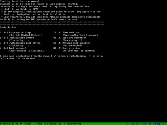
Installation in text mode follows a pattern similar to the graphical installation: There is no single fixed progression; you can configure many settings in any order you want using the main status screen. Screens which have already been configured, either automatically or by you, are marked as [x], and screens which require your attention before the installation can begin are marked with [!]. Available commands are displayed below the list of available options.
Limits of interactive text mode installation include:
-
The installer will always use the English language and the US English keyboard layout. You can configure your language and keyboard settings, but these settings will only apply to the installed system, not to the installation.
-
You cannot configure any advanced storage methods (LVM, software RAID, FCoE, zFCP and iSCSI).
-
It is not possible to configure custom partitioning; you must use one of the automatic partitioning settings. You also cannot configure where the boot loader will be installed.
Installing in the Graphical User Interface
The graphical installation interface is the preferred method of manually installing Fedora. It allows you full control over all available settings, including custom partitioning and advanced storage configuration, and it is also localized to many languages other than English, allowing you to perform the entire installation in a different language. The graphical mode is used by default when you boot the system from local media (a CD, DVD or a USB flash drive).
The sections below discuss each screen available in the installation process. Note that due to the installer’s parallel nature, most of the screens do not have to be completed in the order in which they are described here.
Each screen in the graphical interface contains a Help button. This button opens the Yelp help browser displaying the section of the Fedora Installation Guide relevant to the current screen.
You can also control the graphical installer with your keyboard. Use Tab and Shift+Tab to cycle through active control elements (buttons, check boxes, etc.) on the current screen, Up and Down arrow keys to scroll through lists, and Left and Right to scroll through horizontal toolbars or table entries. Space or Enter can be used to select or remove a highlighted item from selection and to expand and collapse drop-down menus.
Additionally, elements in each screen can be toggled using their respective shortcuts. These shortcuts are highlighted (underlined) when you hold down the Alt key; to toggle that element, press Alt+X, where X is the highlighted letter.
Your current keyboard layout is displayed in the top right hand corner. Only one layout is configured by default; if you configure more than layout in the Keyboard Layout screen (Keyboard Layout), you can switch between them by clicking the layout indicator.
欢迎界面和语言选择
在图形化安装程序启动后显示的第一屏就是欢迎界面。
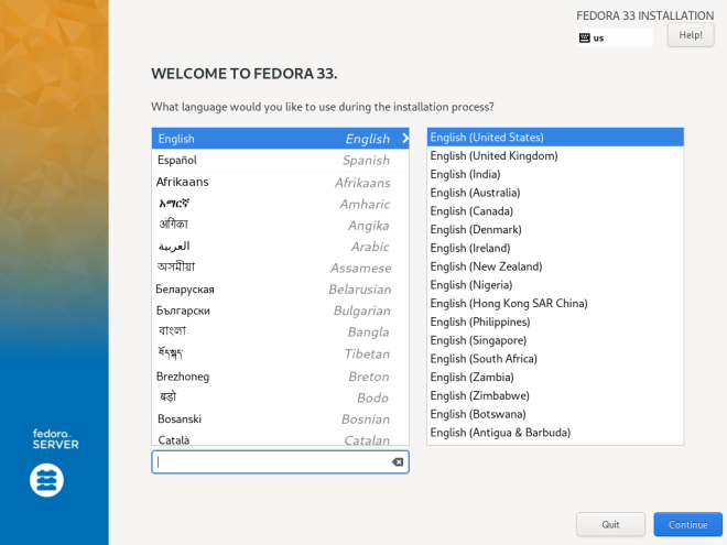
首先在左侧的栏目选择你偏好的语言,然后从右侧的栏目选择你的地区。如果你不想耗费时间在近七十种语言中寻找你的语言,你可以使用左下角的输入框进行搜索。
你所选择的语言会被设定为图形安装程序的显示语言,在安装的全程被使用,也会作为安装后系统的默认语言。尽管你可以在未来修改系统的语言,但是一旦你在这里点击继续,你就不能再回去重新制定安装程序的语言了。
我们会为你默认挑选一种语言,如果你的网络连接在这个时候已经可用了(例如你在网络服务器上引导了安装介质),我们就会通过 GeoIP 模组探测你的位置并将相应的语言设定为默认。指定默认语言的方式还包括在引导选项或者 PXE 服务器配置添加 inst.lang= 。默认语言会出现在语言列表顶部,但是你依然可以在操作选单任意指定其它的语言以用于后续安装和使用。
在选择好语言和地区后,点击继续以确认你的选择然后前往 安装摘要页 。
|
如果你在使用 Fedora 的预发布版本,在点击继续后会有提示框出现告知你你使用的介质是预发布的。此时你可以选择继续安装,或者退出安装重启系统。 |
安装摘要
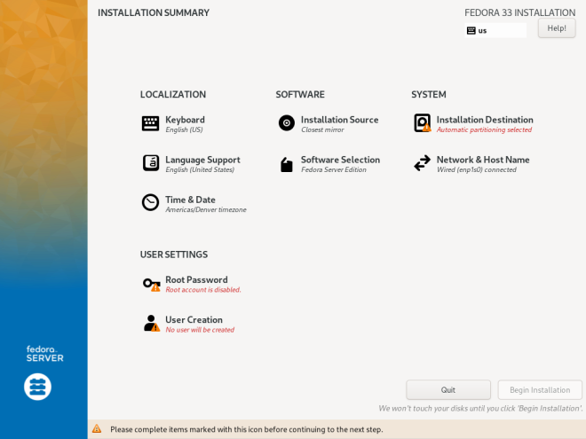
安装摘要页面在安装程序中处于枢纽的地位,绝大多数的安装选项都可以从这里访问。
|
如果你通过引导选项或者 Kickstart 配置文件指定安装来源为网络上的软件仓库,然而网络在安装开始的时候却不可用,那么安装程序将会在显示安装摘要页面之前显示网络配置页面。 |
安装摘要页面包含了若干个跳转到其它页面的链接,这些链接以类别的形式组织起来。对于每一个链接,都有着下面几种状态:
-
图标旁边显示着 警告标志 (带有感叹号的黄色三角形)意味着在开始安装之前需要额外留意这个页面。通常安装路径页面对应的链接在初始时就是这样的,尽管有自动分区功能,但我们仍然要求你至少进入这个页面进行确认,哪怕你什么都不修改。
-
链接文字 变灰 意味着安装程序正在对这个页面的选项进行设置,在访问这个页面之前你必须等待安装程序完成有关的设置。当你修改了安装来源后通常就会有这种情况发生,这是因为安装程序会花上一点时间探测新的安装来源并获取可用软件包列表。
-
链接文字 黑色且无警告标志 意味着这个页面无需你的特别留意。你依然可以进入这个页面并进行一些改动,但是这对于完成安装来说不再是必要的。这常见于区域设置页面,因为这个页面的选项基本都被预先探测或在欢迎页配置妥当了。
页面底部显示有警告信息,开始安装按钮被禁用,这意味着存在没有完成配置的选项。
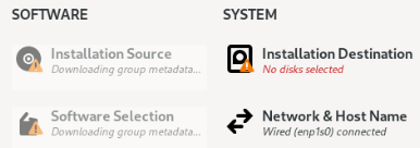
每个页面的标题下方都有解释性的文字,显示当前页面已经配置的内容。有时候显示出来的内容会被精简,在必要的时候可以将鼠标移到上面以获得完整的文字内容。

当你配置好安装所需的一起事物,你就可以点击开始安装按钮以安装 Fedora 。这会将你重定向到 安装进程 页面。请注意在点击这个按钮之前,我们不会对你的硬盘作任何的改动。你可以随时退出安装程序,此时我们会撤销你所有的设置并为你重启系统。
日期时间
“日期时间”屏幕允许你外自己的操作系统配置日期和时间相关的设置。这个屏幕被你选择的欢迎页和语言选择设置项所自动配置,但你仍然可以在开始安装之前修改你的日期、时间和时区设置。

首先,点击屏幕的左上角的下拉菜单来选择你的“地区”。然后,选择你的“城市”,或者最接近你目前所在地点的、在同一时区下的城市。选择一个特定的地点将帮助Fedora确保你的时间总会被设置正确;如果夏令时可用,那么为夏令时而自动做出的时间修改也会被设置正确。
你也可以只选择一个相对于格林尼治时间的时区而不设置到某个特定区域的地点。如果你想这样做,就选择“Etc”作为你的区域。
|
城市和区域列表来自于时区数据库(tzdata)公共域名,它被互联网编号分配机构(IANA)所维护。Fedora项目不能将城市和区域加入这个数据库。你可以在这个链接:https://www.iana.org//time-zones[IANA官方网站]上找到更多信息。 |
在屏幕右上角的拨动开关所示的“网络时间”可以通过使用网络时间协议(NTP)的方式,被用来开启或关闭网络时间同步。只要你的操作系统连上了互联网,开启此功能就会保持你的操作系统的时间正确。默认地,4个NTP_池_会被配置好;此外你也可以通过按下鼠标左键和右键旁边的中键来添加其他的NTP_池_,或者删除默认的NTP_池_。

如果你禁用了网络时间同步,屏幕下方的控件将变得可用,然后你就可以手动设置当前时间和日期了。
在配置完你的时间和日期设置之后,按下屏幕左上角的“Done”按键即可返回安装概要。
键盘布局
`Keyboard Layout`允许您为系统设置一个或多个键盘布局。其中一种键盘布局会根据您在 欢迎和语言选择页面 中的选择自动配置,但您可以在开始安装之前更改此布局并添加其他布局。
键盘布局是独立于系统语言的设置,您可以根据需要分别修改两个设置。
|
此页面中配置的所有设置都会应用到安装后的系统上,同时在安装程序中他们也会立即起作用。 您可以使用任何页面右上角的键盘图标,或您在此页面中配置的键盘选项对键盘布局进行切换。 |
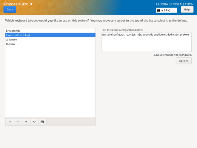
页面的左半部分包含一个列出所有当前配置的布局的窗口。页面上布局的顺序就是切换布局时遵循的顺序,并且第一个列出的布局将是您系统上的默认布局。
屏幕右侧的文本框可用于测试当前选择的布局。
您可以单击列表中的布局以选中它。 在列表的底部,有一组按钮:
-
点
+按钮将添加新的布局。当您按下此按钮时,将打开一个包含按照语言分组的包含所有可用布局的新窗口。 您可以通过浏览列表找到布局,也可以使用此窗口底部的搜索栏。 当您找到要添加的布局时,选中它并按Add。 -
点
-按钮将移除目前选中的布局。 -
上下按钮可用于在列表中向上或向下移动选中的布局。
-
点击键盘按钮则会打开一个新窗口,提供选中的布局的图形表示。
|
如果拉丁字符在您使用的布局中不可用,例如 |
您还可以配置切换可用布局的组合键。 单击屏幕右侧的 Options 按钮打开 Layout Switching Options 对话框,即可配置布局切换使用的组合键。 使用旁边的复选框选择一个或多个组合键,然后单击 OK 以确认您的选择。
完成键盘布局和开关配置后,单击左上角的 Done 返回 Installation Summary 页面。
语言支持
The Language Support screen allows you to configure language settings for your system. The default language is determined by your selection in Welcome Screen and Language Selection and support for this language cannot be removed. You can only add additional languages, which will be available on the installed system - not during the installation.
If you want to change the default language, or the language used during the installation, you must reboot your system, start the installer again, and select a different language in Welcome Screen and Language Selection.
|
Adding support for another language does not automatically configure the corresponding keyboard layout. Layouts are a separate setting configured in Keyboard Layout. |
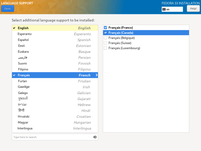
左栏包括了一些可选的语言组,例如英语和中文。如果你从中选择了至少一组,该组语言的左侧就会出现一个勾选标记,这个语言组也会被高亮显示。这样子你就可以很方便地看到哪些语言被配置过了。
要添加一种或多种语言,从左栏选择一个语言组,然后在右栏选择一个具体的语言变种。重复这一步骤,直到所有需要启用的语言都已经配置妥当。
|
Enabling support for some languages (typically languages which use non-Latin script) will install additional packages - for example, enabling support for one or more languages from the |
Once you have made your selections, click Done in the top left corner to return to Installation Summary.
Installation Source
The Installation Source screen allows you to specify a location (local or on the network) from which packages will be downloaded and installed on your system. This screen will be configured automatically in most cases, but you can change your settings or add additional sources.
|
Normally, when you first enter the |
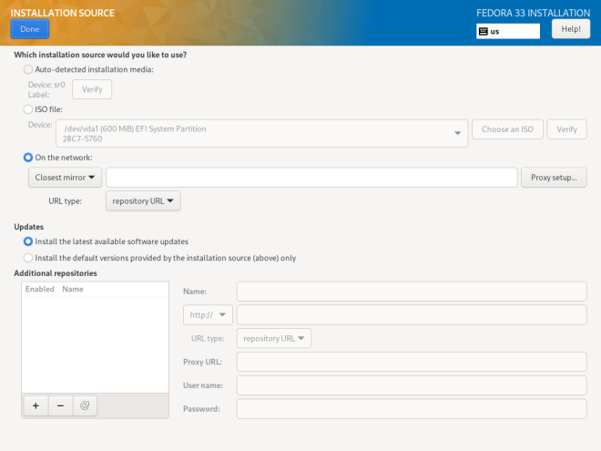
The following options are available. Note that not all of them may be displayed.
- Auto-detected installation media
-
This is the option selected by default if you started the installer from media containing an installation source, such as a live DVD. No additional configuration is necessary. You can click the
Verifybutton check the media integrity. - ISO file
-
This option will appear if the installation program detected a partitioned hard drive with mountable file systems during boot. Select this option, click the Choose an ISO button, and browse to the installation ISO file’s location on your system. You can click the
Verifybutton to check the file’s integrity. - On the network
-
Use this option to download packages to be installed from a network location instead of local media. This is the default selection on network installation media.
In most cases, the
Closest mirroroption available from the protocol selection drop-down menu is preferable. If this option is selected, packages for your system will be downloaded from the most suitable location (mirror).To manually configure a network-based installation source, use the drop-down menu to specify the protocol to be used when downloading packages. This setting depends on the server you want to use. Then, type the server address (without the protocol) into the address field. If you choose NFS, a second input field will appear where you can specify custom
NFS mount options.When selecting an NFS installation source, you must specify the address with a colon (
:) character separating the host name from the path. For example:server.example.com:/path/to/directoryTo configure a proxy for an HTTP or HTTPS source, click the Proxy setup button. Check
Enable HTTP proxyand type the URL into theProxy URLbox. If the proxy server requires authentication, checkUse Authenticationand enter your user name and password. Click OK to finish the configuration.If your HTTP or HTTPS URL refers to a repository mirror list, mark the check box under the address field.
You can also specify additional repositories in the Additional repositories section to gain access to more installation environments and software add-ons. All environments and add-ons will be available for selection in Software Selection once you finish configuring the sources.
To add a repository, click the + button. To delete a repository, select one in the list and click the - button. Click the arrow icon to revert to the previous list of repositories, i.e. to replace current entries with those that were present at the time you entered the Installation Source screen. To activate or deactivate a repository, click the check box in the Enabled column at each entry in the list.
You can name your additional repository and configure it the same way as the primary repository on the network using the input fields on the right side of the section.
Once you have selected your installation source, click Done in the top left corner to return to Installation Summary.
Software Selection
The Software Selection screen allows you to choose a Base Environment and Add-ons. These options control which software packages will be installed on your system during the installation process.
This screen is only available if Installation Source is properly configured and only after the installer has downloaded package metadata from the source.
|
It is not possible to select specific packages during a manual installation. You can only select pre-defined environments and add-ons. If you need to control exactly which packages are installed, you must use a Kickstart file and define the packages in the %packages section. See Automating the Installation with Kickstart for information about Kickstart installations. |
The availability of environments and add-ons depends on your installation source. By default, the selection depends on the installation media you used to start the installation; Fedora Server installation image will have different environments and add-ons available for selection than, for example, the Fedora Cloud image. You can change this by configuring a different installation source containing different environments.
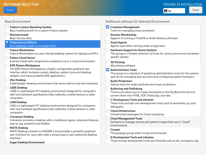
To configure your software selection, first choose an environment on the left side of the screen. Only one environment can be chosen, even if more are available. Then, on the right side of the screen, select one or more add-ons which you want to install by marking the check boxes next to each add-on.
The list of add-ons is divided into two parts by a horizontal line. Add-ons above this line are defined as part of your chosen environment; if you select a different environment, the add-ons available here will change. The add-ons displayed below the separator are not specific to your chosen environment.
Environments and add-ons are defined using a comps.xml file in your installation source (for example, in the repodata/ directory on the full Fedora Server installation DVD). Review this file to see exactly which packages will be installed as part of a certain environment or add-on. For more information about the comps.xml file, see %packages (required) - Package Selection.
After you finish configuring your software selection, click Done in the top left corner to return to Installation Summary.
安装目标位置
安装目标页面将允许你对储存设备进行配置,你可以选择将哪个设备用于 Fedora 的安装。你需要至少选择一个设备以完成安装。
关于Linux 磁盘分区背后的理论知识详见推荐的安装方案。
|
如果你需要使用一个已经包含一些数据的磁盘,例如你希望将 Microsoft Windows 的分区压缩并在剩余的空间上安装 Fedora ,或者你希望升级你的 Fedora ,那么你必须对所有重要的数据做好备份。手动分区是有风险的:如果手动分区进程被中断或是无法完成(例如安装出错、电源中断等等),那么磁盘上已有的数据将可能无法恢复。 |
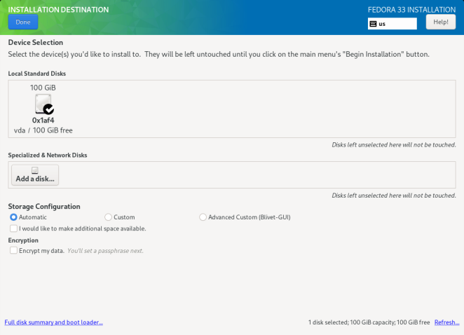
所有在本地可用的储存设备都会在页面的顶部的`本地标准磁盘`区域被列出来(包括 SATA、IDE 和 SCSI 硬盘、USB 驱动器等等)。在安装程序启动的时候本地储存设备就会被自动探测,在安装开始后才连上的设备不会被显示。
如果你需要添加额外的本地储存设备,那么你可以点击右下角的`刷新`按钮,然后你需要按照出现的对话框的说明来进行操作。所有被检测到的磁盘,包括新探测到的磁盘,都会在`本地标准磁盘`区域当中显示出来。
`特殊磁盘和网络磁盘`区域显示着已经配置的网络储存设备(例如 iSCSI 和 FCoE 磁盘)。当你首次打开这个页面的时候,这个区域会是空的,网络设备也不会被自动探测。要搜索网络储存设备,点击添加磁盘按钮并按照 安装目标 - 特殊磁盘与网络磁盘 章节进行操作。所有配置好的网络储存设备都会出现在`特殊磁盘和网络磁盘`区域中。
我们使用一个黑色实心圆为底的白色对勾标记将被用于安装Fedora的储存设备。没有被标记的设备将不会用于安装,自动分区的时候也会忽略这些设备,手动分区的时候这些设备也将会是不可用状态。
|
外接硬盘和闪存盘等 USB 储存设备也会在本地标准磁盘栏目显示,它们跟内部硬盘一样可在安装时供选择。除非你真的想这样做,否则务必 不要 将可卸载设备作为安装目标。如果你在可卸载设备上安装了 Fedora 并移除了设备,那么你的系统可能就不可用了。 |

在选择 Fedora 使用的硬盘后,从储存设定栏目中选择一项:
-
自动 - 如果你选择了这一项,在点击页面左上角的完成按钮后,安装程序就会计算选择磁盘的可用空间,并创建合适的基于 Btrfs 的分区方案。具体的分区方案与你在使用 BIOS 模式还是使用 UEFI 模式有关,也跟磁盘可用的空间相关。我们不会创建基于磁盘的交换分区,而是会创建基于 ZRAM 的交换分区。
在选择自动分区方案时,你可以选择下方的`我想令额外的空间可用`选项。选择这个选项后你就可以从已有的分区中回收空间。例如说如果你的磁盘已经包含了一个不同的操作系统,你就可以通过压缩这个操作系统的分区以为 Fedora 留出更多储存空间。我们会在后面进一步说明回收空间功能。
-
自定义- 如果你选择了这一项,那么你就可以在点击页面左上角的完成按钮后通过半手动配置的形式完成系统分区。这需要你了解磁盘分区背后的概念和理论知识,但是自定义分区将允许你以其他的方式安装系统。有关自定义分区的说明详见手动分区。 -
高级自定义(Blivet图形界面)——选择此选项后点击页面左上角的`完成`按钮来对系统进行真正意义上的手动分区。这需要熟悉磁盘分区背后的概念和理论知识,且操作不受限。
此外你还可以选择`加密我的数据`,此选项将使用 LUKS 加密所有的分区(除了使用_Linux统一密钥设置_ (LUKS)的、用于系统引导的分区,如 /boot)。关于LUKS加密方式详见[citetitle]Fedora 安全 指南, available at https://docs.fedoraproject.org/。
|
如果你丢失了 LUKS 密钥,那么加密的分区上的数据将彻底无法访问。一般而言无法恢复丢失的密钥,然而,如果你是通过 Kickstart 进行的安装,你可以在安装的时候储存你的密钥并创建一个备用的密钥。Kickstart安装详见 使用 Kickstart 进行无人职守安装。 |
要指定在哪些储存设备安装 引导程序 ,就需要点击页面左下角的磁盘概览和引导器链接,并按照 安装引导程序小节的说明进行操作。请注意大部分时候只需要使用默认配置就可以了,但有些配置(例如需要链式引导启动的时候)还是需要手动指定引导的设备。
在选择储存设备、指定自动分区或手动分区、配置磁盘加密和bootloader的位置后,点击左上角的`完成`按钮。然后根据你的选择将发生以下事件:
-
如果你选择加密你的磁盘,那么将会弹出一个`磁盘加密密钥`对话框提示你对密钥进行设置,你只需要在`密钥`和`确定`区域中输入一次密钥,然后再输入一次密钥以确认你的输入无误即可。在输入密钥时会检查密钥的强度,并在密码强度弱时给出如何加强密钥强度的建议。创建强密码详见[citetitle]Fedora安全 指南。
-
如果你选择了自动分区和`我希望令希望额外空间可用`,或者你的磁盘已经没有足够的空间可供安装Fedora,那么`回收磁盘空间`对话框将会出现。对话框将列出你配置的磁盘和磁盘上的所有分区。对话框的右下角显示了目前系统的可用空间以及安装系统至少需要回收的空间。
如果你使用`回收磁盘空间`对话框来*删除*一个分区,那么这个分区上的所有数据都会丢失。如果你希望保留你的数据,请使用`压缩`选项,而不使用`删除`选项。
首先,对可用设备和分区列表进行检查。对于每一项我们都会显示你可以回收多少的空间。`可回收的空间`显示了每个入口可以被回收的空间。要对空间进行回收,选择一个磁盘或分区,你可以点击`删除`按钮删除分区(或磁盘上的所有分区),或者点击`压缩`按钮以在利用分区空闲空间的同时保留原有的数据。你也可以点击右下角的`全部删除`按钮,这将会删除所有磁盘的所有分区并将腾出来的空间全部用于 Fedora 。但与此同时,所有磁盘上的数据都会被删除。
在你为Fedora释放了足够的空间之后,你就可以点击`回收空间`按钮以完成。
在 安装概览 页点击开始安装按钮之前,你在回收空间对话框所做的操作都不会被实际地执行。`回收空间`对话框只*标记*了用于调整大小或删除的分区,但这种操作不会被立刻执行。
-
如果你选择的是`自定义`分区选项,那么在点击`完成`后就会进入`手动分区`页面。详见手动分区。
Boot Loader Installation
Fedora uses GRUB2 (GRand Unified Bootloader version 2) as its boot loader. The boot loader is the first program that runs when the computer starts and is responsible for loading and transferring control to an operating system. GRUB2 can boot any compatible operating system (including Microsoft Windows) and can also use chain loading to transfer control to other boot loaders for unsupported operating systems.
|
Installing GRUB2 may overwrite your existing boot loader. |
If you have other operating systems already installed, the Fedora installer will attempt to automatically detect and configure the boot loader to start them. You can manually configure any additional operating systems after you finish the installation, if they are not detected properly. For instructions on editing GRUB2 configuration, see the Fedora System Administrator’s Guide.
If you are installing Fedora system with more than one disk, you may want to manually specify where the bootloader should be installed. Click the Full disk summary and bootloader link at the bottom of the Installation Destination screen. The Selected Disks dialog will appear. The bootloader will be installed on the device of your choice, or on a UEFI system, the EFI system partition will be created on that device during guided partitioning.
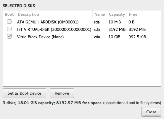
In the Boot column, a “tick” icon marks one of the devices as the intended boot device. To change the boot device, select a device from the list and click the Set as Boot Device button to install the boot loader there instead. Only one device can be set as the boot device.
To decline installation of a new boot loader, select the device currently marked for boot and click the Do not install bootloader button. This will remove the tick and ensure GRUB2 is not installed on any device.
|
If you choose not to install a boot loader for any reason, you will not be able to boot the system directly, and you must use another boot method, such as a stand-alone commercial boot loader application. Use this option only if you are sure you have another way to boot your system. |
The boot loader may also require a special partition to be created, depending on whether your system uses BIOS or UEFI firmware and also depending on whether the boot drive has a GUID Partition Table (GPT) or a Master Boot Record (MBR, also known as msdos) label. If you use automatic partitioning, the installer will create this partition if needed. For details, see Recommended Partitioning Scheme.
Installation Destination - Specialized & Network Disks
This part of the Installation Destination screen allows you to configure non-local storage devices, namely iSCSI and FCoE storage. This section will mostly be useful to advanced users who have a need for networked disks. For instructions on setting up local hard drives, see Installation Destination.
|
This section only explains how to make existing network disks available inside the installer. It does not explain how to set up your network or a storage server, only how to connect to them. |
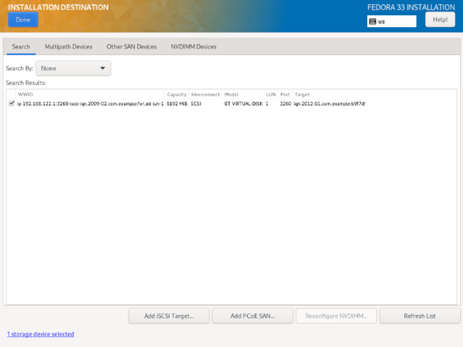
The screen contains a list of all currently available (discovered) network storage devices. When the screen is opened for the first time, the list will be empty in most cases because no network storage has been discovered - the installer makes no attempt at discovering this unless you configure network disks using a Kickstart file.
To add one or more storage devices to the screen so you can search them and use them in the installation, click Add iSCSI Target or Add FCoE SAN in the bottom right corner of the screen, and follow the instructions in Add iSCSI Target or Add FCoE SAN, depending on which type of network storage you want to add.
Network storage devices successfully discovered and configured by the installer will then be displayed in the main list, along with identifying information such as Name, WWID, Model and Target. To sort the list by a specific column (for example WWID), click the column’s heading.
|
On lower display resolutions, the list may be too wide to fit on the screen, and some of the columns or buttons may be hidden initially. Use the horizontal scroll bar at the bottom of the list to move your view and see all available table columns and controls. |
There are three tabs on the top of the list, which display different information:
- Search
-
Displays all available devices, regardless of their type, and allows you to filter them either by their World Wide Identifier (WWID) or by the port, target, or logical unit number (LUN) at which they are accessed.
- Multipath Devices
-
Storage devices accessible through more than one path, such as through multiple SCSI controllers or Fiber Channel ports on the same system.
The installation program only detects multipath storage devices with serial numbers that are 16 or 32 characters long.
- Other SAN Devices
-
Devices available on a Storage Area Network (SAN).
Depending on the tab you are currently in, you can filter the discovered devices by using the Filter By field. Some of the filtering options are automatically populated based on discovered devices (for example, if you select Filter By: Vendor, another drop-down menu will appear showing all vendors of all discovered devices). Other filters require your input (for example when filtering by WWID), and present you with a text input field instead of a drop-down menu.
In the list (regardless of how it is filtered), each device is presented on a separate row, with a check box to its left. Mark the check box to make the device available during the installation process; this will cause this device (node) to be shown in the Specialized & Network Disks section in Installation Destination. There, you can select the disk as an installation target and proceed with either manual or automatic partitioning.
|
Devices that you select here are not automatically wiped by the installation process. Selecting a device on this screen does not, in itself, place data stored on the device at risk. Also note that any devices that you do not select here to form part of the installed system can be added to the system after installation by modifying the |
When you have selected the storage devices to make available during installation, click Done to return to Installation Destination.
Add iSCSI Target
To use iSCSI storage devices, the installer must be able to discover them as iSCSI targets and be able to create an iSCSI session to access them. Both of these steps may require a user name and password for Challenge Handshake Authentication Protocol (CHAP) authentication.
You can also configure an iSCSI target to authenticate the iSCSI initiator on the system to which the target is attached (reverse CHAP), both for discovery and for the session. Used together, CHAP and reverse CHAP are called mutual CHAP or two-way CHAP. Mutual CHAP provides the greatest level of security for iSCSI connections, particularly if the user name and password are different for CHAP authentication and reverse CHAP authentication.
Follow the procedure below to add an iSCSI storage target to your system.
-
Click the
Add iSCSI Targetbutton in the bottom right corner of the Installation Destination - Specialized & Network Disks screen. A new dialog window titledAdd iSCSI Storage Targetwill open. -
Enter the IP address of the iSCSI target in the
Target IP Addressfield. -
Provide a name in the
iSCSI Initiator Namefield for the iSCSI initiator in iSCSI Qualified Name (IQN) format. A valid IQN entry contains:-
The string
iqn.(including the period). -
A date code specifying the year and month in which your organization’s Internet domain or subdomain name was registered, represented as four digits for the year, a dash, and two digits for the month, followed by a period. For example, represent September 2010 as
2010-09. -
Your organization’s Internet domain or subdomain name, presented in reverse order (with the top-level domain first). For example, represent the subdomain storage.example.com as
com.example.storage. -
A colon (
:) followed by a string which uniquely identifies this particular iSCSI initiator within your domain or subdomain. For example,:diskarrays-sn-a8675309A complete IQN will therefore look as follows:
iqn.2010-09.com.example.storage:diskarrays-sn-a8675309An example using the correct format is also displayed below the input field for reference.
For more information about IQNs, see 3.2.6. iSCSI Names in RFC 3720 - Internet Small Computer Systems Interface (iSCSI), available from https://tools.ietf.org/html/rfc3720#section-3.2.6 and 1. iSCSI Names and Addresses in RFC 3721 - Internet Small Computer Systems Interface (iSCSI) Naming and Discovery, available from https://tools.ietf.org/html/rfc3721#section-1.
-
-
Specify the type of authentication to use for iSCSI discovery using the
Discovery Authentication Typedrop-down menu. Depending on which type of authentication you selected, additional input fields (such asCHAP UsernameandCHAP Passwordmay then become visible. Fill in your authentication credentials; these should be provided by your organization. -
Click the
Start Discoverybutton. The installer will now attempt to discover an iSCSI target based on the information you provided, and if the target requires CHAP or reverse CHAP authentication, it will attempt to use the credentials you provided. This process may take some time (generally less than 30 seconds), depending on your network.If the discovery was not successful, an error message will be displayed in the dialog window. This message will vary based on which part of the discovery failed. If the installer did not find the target you specified at all, you should check the IP address; if the problem is an authentication error, make sure you entered all CHAP and reverse CHAP credentials correctly and that you have access to the iSCSI target.
The
No nodes discoverederror message may also mean that all nodes on the address you specified are already configured. During discovery, Anaconda ignores nodes which have already been added.If the discovery was successful, you will see a list of all discovered nodes.
-
Select one or more nodes you want to log in to by marking or unmarking the check box next to each node discovered on the target. Below the list, select again the type of authentication you want to use; you can also select the
Use the credentials from discoveryoption if the CHAP/reverse CHAP user name and password you used to discover the target are also valid for logging in to it.After selecting all nodes you want to use, click
Log Into initiate an iSCSI session. Anaconda will attempt to log in to all selected nodes. If the login process is successful, theAdd iSCSI Storage Targetdialog will close, and all nodes you have configured will now be shown in the list of network disks in Installation Destination - Specialized & Network Disks.
You can repeat this procedure to discover additional iSCSI targets, or to add more nodes from a previously configured target. However, note that once you click the Start Discovery button for the first time, you will not be able to change the iSCSI Initiator Name. If you made an error when configuring the initiator name, you must restart the installation.
Add FCoE SAN
The following procedure explains how to add Fibre Channel over Ethernet (FCoE) storage devices and make them available during the installation:
-
Click the
Add FCoE SANbutton in the bottom right corner of Installation Destination - Specialized & Network Disks. A new dialog window will open. -
Select the network interface (
NIC) which is connected to your FCoE switch from the drop-down menu. Note that this network interface must be configured and connected - see Network & Hostname. -
Below the
NICdrop-down menu are two choices:Use DCB-
Data Center Bridging (DCB) is a set of enhancements to the Ethernet protocols designed to increase the efficiency of Ethernet connections in storage networks and clusters. This option should only be enabled for network interfaces that require a host-based DCBX client. Configurations on interfaces that implement a hardware DCBX client should leave this check box empty.
Use auto vlan-
This option indicates whether VLAN discovery should be performed. If this box is checked, then the FCoE Initiation Protocol (FIP) VLAN discovery protocol will run on the Ethernet interface once the link configuration has been validated. If they are not already configured, network interfaces for any discovered FCoE VLANs will be automatically created and FCoE instances will be created on the VLAN interfaces. This option is enabled by default.
-
After you select which interface and options to use, click
Add FCoE Disk(s). Discovered FCoE storage devices will be displayed under theOther SAN Devicestab in Installation Destination - Specialized & Network Disks.
Manual Partitioning
The Manual Partitioning screen allows you to create a storage configuration for your Fedora system manually, giving you a greater control over your system’s storage.
In most other installers for both Linux and other operating systems, disk partitioning usually takes a “bottom-up” approach. In these installers, you first create underlying devices such as LVM physical volumes, then you create a layout such as LVM on top of them, then you create file systems on top of logical volumes, and the last step is usually assigning a mount point to each volume as needed.
Anaconda uses an opposite approach. First, you create all separate mount points you need, and everything needed to create them (creating a volume group, logical volumes inside it, and physical volumes where the volume group will reside) is performed automatically. You can then adjust the automatic settings as you require.
|
No permanent changes will be made to your disks during the actual partitioning process. The configuration you have selected will only be written to your system after you press the |
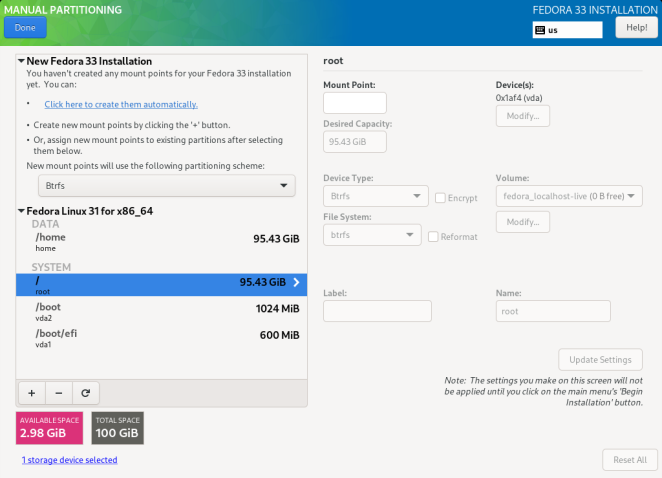
When you first open the Manual Partitioning screen, the column on the left side will display all previously existing partitions on all drives which you selected as installation targets in Installation Destination. If none of the selected drives contain any existing partitions, then a message informing you that no mount points currently exist will appear.
Here, you can choose a partitioning scheme such as LVM or BTRFS and click the Click here to create them automatically to prompt the installer to create a basic partitioning layout; this layout follows the guidelines described in Recommended Partitioning Scheme. The created layout is a basic layout where partition/volume sizes are determined automatically based on the total amount of available space.
Click the + button to add a mount point. In the dialog window that opens, choose a mount point such as / or /home, and the desired capacity for the mount point (such as 10GB or 500MB). Note that specifying the mount point is mandatory, but you do not have to specify the capacity at this point; this is useful when adding a mount point which you want to make larger than the current available space permits. Then, click Add mount point to add it to the list using the default settings, which means it will be created as a logical volume, and a new volume group will be created for it unless one already exists.
Then, select the newly created mount point in the list on the left side. A set of controls will display on the right side of the screen, allowing you to change its mount point, the device on which it will physically reside, its capacity, file system, etc. When you change any settings, press Update Settings on the bottom right. This will save the adjusted configuration; you can now create another mount point, or select a different existing one and adjust its settings as well.
|
For a description of available device and file system types, see Device, File System and RAID Types. |
To remove a mount point, select it in the list and press the - button below.
The exact steps for configuring your storage depend on your specific needs and your system configuration. Procedures for creating specific layouts are described further in this chapter. Before you start, you should also review Recommended Partitioning Scheme and Advice on Partitions for a list of requirements and tips for partitioning your disks for Fedora.
Below the list of existing mount points are two fields, showing you how much free space is left on your storage devices and how much total space they have.
Click the X storage devices selected to view a summary of currently selected storage devices; this may help you with orientation in more complicated storage schemas. Devices displayed here are the ones you have selected in Installation Destination. If you want to add or remove any storage devices from your configuration, return to that screen and change your selection.
You can press the Reset All button in the bottom right corner at any time to reset the storage configuration to the state it was in when you last opened the Manual Partitioning screen. This means that if you modify the storage configuration, leave the screen, and then come back, the Reset button will reset the configuration back to the already modified state, discarding only the changes you have made recently, not all changes to the storage configuration since you booted the installer.
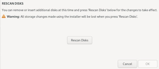
To discard all changes, and to also detect any new drives which have not been detected when the installer started (usually when you attached a new drive after you started), press the button marked by a circular arrow in the set of controls below the list of mount points on the left side of the screen. In the dialog window that opens, press Rescan Disks and wait until the scanning process completes. Then, press OK to return to Installation Destination; all detected disks including any new ones will be displayed in the Local Standard Disks section.
After you finish configuring your system storage, press Done in the top left corner to save the configuration and return to the Installation Summary screen. At this point, the installer will check if your storage configuration is valid. If an error was detected, a message will be displayed at the bottom of the screen. Click the message to open a dialog window explaining what kind of error has been detected (for example, you put /boot on a Btrfs subvolume, or you did not create a BIOS Boot partition when your system requires one).
If such a message is displayed, go back and fix any issues found by the installer; otherwise you will not be able to proceed with the installation. You can also press Done again to return to the Installation Summary anyway, but a storage configuration error will prevent you from starting the actual installation process.
If no error message is displayed and if you made any changes since the last time you have visited this screen, a summary dialog will appear, displaying a detailed list of the changes you made. Review the list and click Accept Changes to proceed with Installation Summary, or click Cancel & Return to Custom Partitioning if you want to make any more changes.
Creating Standard Partitions
Standard partitions are the most common type of partition, with the widest support across operating systems. For example, Microsoft Windows uses exclusively physical partitions and cannot natively work with LVM or Btrfs. Most Fedora partitioning setups will also require at least one standard partition for the /boot directory, and possibly also another standard partition with the BIOS Boot or EFI System file system to store the boot loader.
See An Introduction to Disk Partitions for additional information about the concepts behind physical partitions.
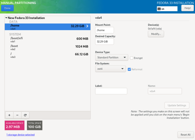
Follow the procedure below to create mount points on standard physical partitions:
-
按下现存挂载点列表底部的“+"按钮,然后将开启一个新的对话框。
-
In the new dialog window, specify a mount point for which you want to create a separate mount point - for example,
/. Optionally, specify a size for the partition using standard units such as MB or GB (for example,50GB). Then, clickAdd mount pointto add the mount point and return to the main partitioning screen.When creating a swap partition, specify the mount point as
swap. For a BIOS Boot partition, usebiosboot. For an EFI System Partition, use/boot/efi.For information about these partition types, see Recommended Partitioning Scheme.
-
The mount point has now been created using the default settings, which means it has been created as an LVM logical volume. Select the newly created mount point in the left pane to configure it further, and convert it to a physical partition by changing the
Device Typeoption toStandard Partition. Then, clickUpdate Settingsin the bottom right corner of the screen. -
In the
Device(s)section on the right side of the screen, you can see that the partition has been assigned to one or more hard drives. Click theModifybutton to configure on which drive this partition will be created. -
In the
Configure Mount Pointdialog, you can specify which physical devices (disks) this volume may reside on. You can select one or more disks which will be used to hold this volume by holding down Ctrl and clicking each disk in the list. If you select multiple disks here, Anaconda will determine where exactly the partition should be created based on how you configured the rest of the installation. If you want to make sure that this partition is placed on a specific hard drive, select only that drive and unselect all others.After you finish configuring the partition’s location, click
Saveto return to the mainManual Partitioningscreen. -
Configure other settings specific to the partition - its
Mount Point,Desired Capacity, andFile System. PressUpdate Settingsto apply any changes to the configuration.
Repeat this procedure for any additional standard partitions you want to create.
Creating Software RAID
Redundant arrays of independent disks (RAIDs) are constructed from multiple storage devices that are arranged to provide increased performance and, in some configurations, greater fault tolerance. See Device, File System and RAID Types for a description of different kinds of RAIDs.
A RAID device is created in one step, and disks are added or removed as necessary. One RAID partition per physical disk is allowed for each device, so the number of disks available to the installation program determines which levels of RAID device are available to you. For example, if your system has two hard drives, the installation program will not allow you to create a RAID10 device, which requires 4 separate partitions.
|
This section only explains how to create software RAID with standard (physical) partitions. However, you can also configure LVM volume groups and Btrfs volumes to use RAID and place their logical volumes or Btrfs subvolumes on top of this RAID array. See Creating a Logical Volume Management (LVM) Layout and Creating a Btrfs Layout for instructions on creating RAID in LVM and Btrfs. |
|
RAID configuration options are only visible if you have selected two or more disks for installation. At least two disks are required to create a RAID device, and some RAID layouts will require more. Requirements for different types of RAID are described in Device, File System and RAID Types. |
Follow the procedure below to create software RAID:
-
按下现存挂载点列表底部的“+"按钮,然后将开启一个新的对话框。
-
In the new dialog window, specify a mount point for which you want to create a separate software RAID partition - for example,
/. Optionally, specify a size for the new partition using standard units such as MB or GB (for example,50GB). Then, clickAdd mount pointto add the mount point and return to the main partitioning screen.When creating a mount point for swap on software RAID, specify the mount point as
swap. -
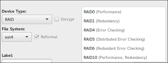
The mount point has now been created using the default settings, which means it has been created as an LVM logical volume. Select the newly created mount point in the left pane to configure it further, and convert it to a software RAID partition by changing the
Device Typeoption toRAID. -
Choose a RAID type from the
RAID Leveldrop-down menu. Available RAID types and their requirements are described in Device, File System and RAID Types. -
In the
Device(s)section on the right side of the screen, you can see that the partition has been assigned to several physical disks. Click theModifybutton to configure on which drives this partition will be created. -
In the
Configure Mount Pointdialog, you can specify which physical devices (disks) this partition may reside on. You can select one or more disks which will be used to hold this partition by holding down Ctrl and clicking each disk in the list. If you want to make sure that this partition is placed on a specific set of hard drives, select only those drives and unselect all others.After you finish configuring the partition’s location, click
Saveto return to the mainManual Partitioningscreen. -
Configure other settings specific to the partition - its
Mount Point,Desired Capacity, andFile System. PressUpdate Settingsto apply any changes to the configuration.
Repeat this procedure for any additional standard partitions with software RAID you want to create.
Creating a Logical Volume Management (LVM) Layout
Logical Volume Management (LVM) presents a simple logical view of underlying physical storage space, such as hard drives or LUNs. Partitions on physical storage are represented as physical volumes that can be grouped together into volume groups. Each volume group can be divided into multiple logical volumes, each of which is analogous to a standard disk partition. Therefore, LVM logical volumes function as partitions which can span multiple physical disks.
See Understanding LVM for additional information about the concepts behind Logical Volume Management.
|
Some partition types - notably the |
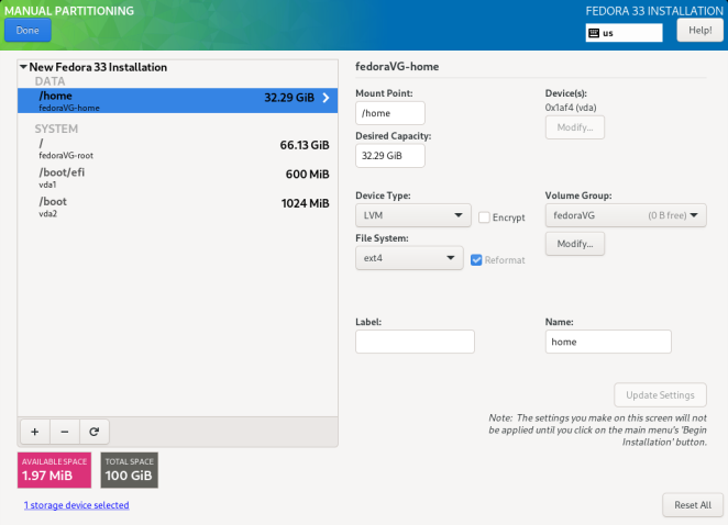
Follow the procedure below to create LVM logical volumes and volume groups.
-
按下现存挂载点列表底部的“+"按钮,然后将开启一个新的对话框。
-
In the new dialog window, specify a mount point for which you want to create a separate logical volume - for example,
/. Optionally, specify a size for the volume using standard units such as MB or GB (for example,50GB). Then, clickAdd mount pointto add the volume and return to the main partitioning screen.When creating a mount point for swap on LVM, specify the mount point as
swap. -
The mount point has now been created using the default settings, which means it has been created as an LVM logical volume, and a volume group has been created to contain it. Select the newly created mount point in the left pane to configure it further. If you want to use thin provisioning for this volume, change the
Device Typeoption toLVM Thin Provisioning. -
In the
Volume Groupmenu, you can see that the volume has been assigned to an automatically created volume group, which is named after the Fedora variant you are installing (for example,fedora-server. Click theModifybutton under the drop-down menu to access the volume group settings. -
In the
Configure Volume Groupdialog, you can change the volume group’s name, itsRAID level(see Device, File System and RAID Types for information about available RAID types), and you can also specify which physical devices (disks) this volume group should reside on. You can select one or more disks which will be used to hold this volume group by holding down Ctrl and clicking each disk in the list.If you select a redundant RAID type (such as
RAID1 (Redundancy)), the volume group will take up twice its actual size on your disks. A 5 GB volume group with RAID1 will take up 10 GB of space.You can also make sure that the volume group is encrypted by selecting the
Encryptoption; this will enable LUKS encryption for the entire volume group. See the Fedora Security Guide, available at https://docs.fedoraproject.org/, for information about LUKS disk encryption.Additionally, you can set a fixed size for the volume group by selecting the
Fixedoption from theSize policymenu and entering a size for the volume group.After you finish configuring the volume group settings, click
Saveto return to the mainManual Partitioningscreen.The configuration dialog does not allow you to specify the size of the volume group’s physical extents. The size will always be set to the default value of 4 MiB. If you want to create a volume group with different physical extents, create it manually by switching to an interactive shell and using the vgcreate command, or use a Kickstart file with the volgroup --pesize=size command.
-
If you need to create more than one volume group, open the
Volume Groupdrop-down menu and select theCreate a new volume groupoption. A new dialog window will open, identical to the one described in the previous step. Again, select a name, storage devices, encryption settings, RAID level and size policy for the new group, and clickSave. The new volume group will then become available in theVolume Groupdrop-down menu; you can then go through your existing mount points and change this setting to assign them to a different volume group. -
Configure other settings specific to the logical volume - its
Mount Point,Desired Capacity,File System, andName. PressUpdate Settingsto apply any changes to the configuration.
Repeat this procedure for any additional logical volumes you want to create. Note that when creating additional LVM logical volumes, a new volume group is not automatically created each time; instead, any additional volumes are assigned to an existing group.
For each mount point you create, review its settings and make sure that it is assigned to the correct group, that it has sufficient capacity, and that it has a descriptive name so you can identify the volume later if you need to.
创建一个Btrfs布局
_Btrfs_是一种文件系统,但在一个存储设备上有多种特性。它被设计用于令文件系统能够容错、能够查错并且能够修复错误。它使用checksums确保数据和元数据的完整性,并且支持快照,用快照可以实现备份、磁盘对拷和命名空间隔离(例如在容器上的应用)。
创建一个Btrfs布局有点像LVM(详见创建一个逻辑卷管理(LVM) 布局),而只是稍微有一点点术语上的区别。一个Btrfs_卷_和一个LVM卷组是等价的,并且一个Btrfs_子卷_和一个LVM逻辑卷是相似的。需要注意的一点是:如何使用[应用]*Anaconda*上报分离挂载点的大小。对于LVM而言,每个逻辑卷的精确大小在左侧面板的挂载点旁边来显示。但对于Btrfs而言,每个子卷旁边显示的是整个卷的大小。
|
有些分区类型——特别注意BIOS启动分区和EFI分区——不能用Btrfs子卷放置,要用普通逻辑分区来放置它们。详见推荐的分区方案。 |
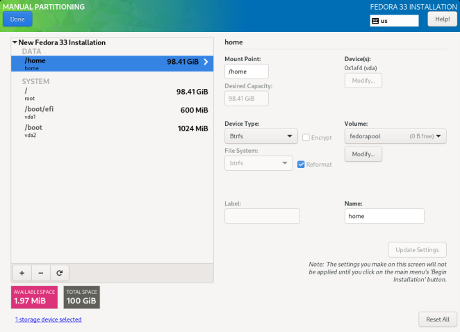
按以下流程来创建Btrfs卷和子卷:
-
按下现存挂载点列表底部的“+"按钮,然后将开启一个新的对话框。
-
在这个新的对话框中,你需要指定一个现存的挂载点来创建分离挂载点——例如:挂载点“/”。Anaconda将对每一个你创建的挂载点都创建一个Btrfs子卷。类似于目录的概念,子卷没有属于它们各自的大小。最后,点击“增加挂载点”来增加子卷,然后返回分区主屏幕。
当在Btrfs上创建一个交换分区挂载点时,需要指定挂载点类型为“swap”。
-
一旦挂载点被创建,选择左侧面板上的、新创建的挂载点,然后在右侧面板上深入配置这个挂载点。在配置完成后,点击屏幕右下角的“更新设置”按钮。
-
在“卷”区域,你可以看到挂载点的子卷已经被配置给了自动创建的卷。点击下拉菜单下方的“修改”按钮来配置卷设置。
-
在“配置卷”对话框中,你可以修改卷标。无论卷是否被加密过,或者卷的“RAID级别”是什么(可用RAID类型详见设备、文件系统和RAID类型),然后你也可以指定这个卷应该放在哪些物理设备(磁盘)之上。你可以通过按Ctrl键并点击鼠标左键的方式来选择一块或多块磁盘来容纳这个卷。
安装器支持对整个Btrfs卷进行LUKS加密。要开启加密,你需要点击卷下方的修改按钮,然后检查加密项。LUKS磁盘加密的信息详见[citetitle]Fedora 安全指导书, available at https://docs.fedoraproject.org/。
此外,你可以通过选择“大小策略”中的“固定大小”的选项、然后对一个卷组输入一个大小参数的方式,来设置卷为一个固定的大小。
在你配置完Btrfs卷的设置之后,点击“保存”来返回主“手动分区”屏幕。
-
如果你需要创建多个Btrfs卷,则需要点开“卷”下拉菜单,然后选择“添加新卷”选项。然后,一个新的对话框将会弹出,之后的操作和上面的步骤中描述的相同:为新卷再次选择卷标、存储设备、加密设置、RAID级别和尺寸策略,最后点击“保存”。新卷随后将在“卷”下拉菜单中可用。此外,你也可以进入先前的挂载点、修改这个设置来将挂载点分配到另一个卷上。
-
配置其他专属于子卷的设置——子卷的“挂载点”、“设备类型”和“卷标”。按下“更新设置”按钮来应用设置中的修改。
对于你想创建的所有Btrfs子卷,你都要重复这个流程。注意:当创建其他的子卷时,不会每次都创建一个新的卷;相反地,新创建的子卷都会默认分配到已有的卷之下。
对于每个你创建的挂载点而言,你需要检查这些挂载点的设置。检查的项目包括:确保挂载点都分配到正确的卷之下;挂载点要有足够的容量;挂载点要有一个描述性的名称,以便您可以识别子卷。
设备、文件系统和RAID类型
Fedora支持多种类型的设备和文件系统。下面的列表提供了一段关于每种可用设备、文件系统、RAID类型和注意事项的简短描述。
要选择一种设备类型、一个分区的文件系统或者一个逻辑卷的文件系统,可以在这个列表手动分区中进行选择。在屏幕右侧的下拉菜单里面选择一个“设备类型”和一个“文件系统”,然后点击“更新设置”。再重复这种操作,直到你想修改的所有的挂载点都改完了为止。
要配置软件RAID,你需要先确保你有足够的物理硬盘来选为安装介质(每种RAID类型需要的不同硬盘的数量在解释信息里面都有注解)。然后,当创建Btrfs卷组或者LVM卷组的时候,选择或者修改一种RAID级别;或者也可以选择“软件RAID”作为设备类型、用标准分区来创建软件RAID。详细说明请见创建Btrfs布局, 创建逻辑卷管理(LVM)布局, and 创建软件RAID,可在需要时进行查阅。
-
“标准分区”——一种可以包含一个文件系统或者交换空间的、标准的分区。标准分区最常见的用途是“/boot”、BIOS启动分区和EFI系统分区。对于其他用途的分区,推荐使用LVM逻辑卷或者Btrfs子卷。详见一段关于磁盘分区的介绍来了解有关于物理分区之外的概念。
-
“LVM”——选择“LVM”作为“设备类型”将创建一个LVM逻辑卷和一个容纳它的卷组(除非有一个卷组已经存在,并且LVM逻辑卷分配给了已有的卷组,此时则不会创建新的卷组)。LVM能改善在使用物理硬盘时的性能,并且允许你通过一个挂载点使用多块硬盘。关于如何创建逻辑卷的信息详见创建一个逻辑卷管理(LVM)布局。并且,其他关于和LVM相关的、总的信息详见理解LVM。
-
LVM自动精简配置——使用自动精简配置技术,你可以管理一个由剩余空间组成的存储池,知名的有_thin pool_,当应用需要时可以被安排空间到一个任意数量的设备。当需要低开销、高效率地分配存储空间时,这个thin pool的存储空间也可以被动态扩展。
-
RAID- Creating two or more software RAID partitions allows you to create a software RAID device. One RAID partition is assigned to each disk on the system. See Creating Software RAID for instructions on creating software RAID. -
BTRFS- Btrfs is a file system with several device-like features. It is capable of addressing and managing more files, larger files, and larger volumes than the ext2, ext3, and ext4 file systems. See Creating a Btrfs Layout for more information about creating Btrfs volumes.
-
ext4- The ext4 file system is based on the ext3 file system and features a number of improvements. These include support for larger file systems and larger files, faster and more efficient allocation of disk space, no limit on the number of subdirectories within a directory, faster file system checking, and more robust journaling. Ext4 is the default and recommended file system used by Fedora Workstation and Cloud. The maximum supported size of a single ext4 file system is 50 TB. -
ext3- The ext3 file system is based on the ext2 file system and has one main advantage - journaling. Using a journaling file system reduces time spent recovering a file system after a crash, as there is no need to check the file system for metadata consistency by running the fsck utility every time a crash occurs. -
ext2- An ext2 file system supports standard Unix file types, including regular files, directories, or symbolic links. It provides the ability to assign long file names, up to 255 characters. -
swap- Swap partitions are used to support virtual memory. In other words, data is written to a swap partition when there is not enough RAM to store the data your system is processing. A swap partition should always be created; see Recommended Partitioning Scheme for details such as the recommended size. -
xfs- XFS is a highly scalable, high-performance file system that supports file systems up to 16 exabytes (approximately 16 million terabytes), files up to 8 exabytes (approximately 8 million terabytes), and directory structures containing tens of millions of entries. XFS also supports metadata journaling, which facilitates quicker crash recovery. The maximum supported size of a single XFS file system is 500 TB. Starting with Fedora 22, XFS is the default and recommended file system on Fedora Server.Note that the size of an XFS file system cannot currently be reduced without destroying and recreating the file system. If you expect that you will need to adjust the sizes of your file systems often, using XFS is not recommended, as it makes administration substantially more time-consuming.
-
vfat- The VFAT file system is a Linux file system that is compatible with Microsoft Windows long file names on the FAT file system. -
BIOS Boot- A very small partition required for booting from a device with a GUID partition table (GPT) on BIOS systems and UEFI systems in BIOS compatibility mode. See Recommended Partitioning Scheme for details. -
EFI System Partition- A small partition required for booting a device with a GUID partition table (GPT) on a UEFI system. See Recommended Partitioning Scheme for details.
-
RAID0 (Performance)- Distributes data across multiple disks. Level 0 RAID offers increased performance over standard partitions and can be used to pool the storage of multiple disks into one large virtual device. Note that Level 0 RAIDs offer no redundancy and that the failure of one device in the array destroys data in the entire array. RAID 0 requires at least two disks. -
RAID1 (Redundancy)- Mirrors all data from one partition onto one or more other disks. Additional devices in the array provide increasing levels of redundancy. RAID 1 requires at least two disks. -
RAID4 (Error Checking)- Distributes data across multiple disks and uses one disk in the array to store parity information which safeguards the array in case any disk within the array fails. Because all parity information is stored on one disk, access to this disk creates a “bottleneck” in the array’s performance. Level 4 RAID requires at least three disks. -
RAID5 (Distributed Error Checking)- Distributes data and parity information across multiple disks. Level 5 RAIDs therefore offer the performance advantages of distributing data across multiple disks, but do not share the performance bottleneck of level 4 RAIDs because the parity information is also distributed through the array. RAID 5 requires at least three disks. -
RAID6 (Redundant Error Checking)- Level 6 RAIDs are similar to level 5 RAIDs, but instead of storing only one set of parity data, they store two sets. RAID 6 requires at least four disks. -
RAID10 (Performance, Redundancy)- Level 10 RAIDs are nested RAIDs or hybrid RAIDs. They are constructed by distributing data over mirrored sets of disks. For example, a level 10 RAID array constructed from four RAID partitions consists of two mirrored pairs of striped partitions. RAID 10 requires at least four disks.
Recommended Partitioning Scheme
In most cases, at least the following mount points should always be created:
/boot- 1 GB-
This partition contains the operating system kernel, which allows Fedora to boot. It also contains other files used during the bootstrap process. Due to the limitations of most firmware, creating a separate, small standard partition for this directory is recommended. In most scenarios, a 1 GB
/bootpartition is adequate.If your system has a hardware RAID controller, be aware that some BIOS types do not support booting from it. In that case, the
/bootpartition must be created on a partition outside of the RAID array, such as on a separate hard drive.Also note that the
/bootdirectory cannot be placed on a LVM logical volume. Use a standard partition. /(root) - 25 GB-
This is where the root directory is located. The root directory is the top level of the directory structure. By default, all files are written to this partition unless a different partition is mounted in the path being written to (for example,
/bootor/home). If you follow the recommended scheme described in this section, this will be the partition where most software packages will be installed.For a minimal installation, a 10 GB root partition will be sufficient. However, for most common installations which include extra packages and a graphical user interface, the root partition should be at least 25 GB; with 75 GB being sufficient for most common use cases.
The
/mount point is the top of the Linux Filesystem Hierarchy, and is referred to as the root file system, or root. The/rootdirectory, sometimes pronounced “slash-root”, is the home directory for therootuser. /home- at least 10 GB-
To store user data separately from system data, create a dedicated mount point for the
/homedirectory. This partition should be sized based on the amount of data that will be stored locally, number of users, and so on. This will allow you to upgrade or reinstall Fedora without erasing user data files. During the installation, a separate/homepartition will be created if there are 50 GB or more free space for your Fedora installation.When using Fedora as a workstation for normal use with a graphical environment, this mount point should have the most disk space assigned to it, as it will likely hold the most data (user settings, images, videos, etc).
- swap - based on your system parameters
-
Swap partitions support virtual memory; data is written to them when there is not enough RAM to store the data your system is processing. This partition’s size is a function of system memory workload, not total system memory, and therefore is not equal to the total system memory size. Therefore, it is important to analyze what applications a system will be running and the load those applications will serve in order to determine the system memory workload. Application providers and developers should be able to provide some guidance.
When the system runs out of swap space, the kernel terminates processes as the system RAM memory is exhausted. Configuring too much swap space results in storage devices being allocated but idle and is a poor use of resources. Too much swap space can also hide memory leaks. The maximum size for a swap partition and other additional information can be found in the
mkswap(8)man page.Beginning with Fedora 33, disk-based swap is no longer created by default. Instead, ZRAM-based swap is automatically used. See
man zram-generatorandman zram-generator.conffor more information. Should you choose to create disk-based swap, you will have two swap devices: disk-based with a lower priority, and ZRAM-based with a higher priority.The table below provides the recommended size of a swap partition depending on the amount of RAM in your system and whether you want sufficient memory for your system to hibernate. If you let the installation program partition your system automatically, the swap partition size will be established using these guidelines. Automatic partitioning setup assumes hibernation is not in use, and the maximum size of the swap partition is limited to 10% of the total size of the hard drive. If you want to set up enough swap space to allow for hibernation, or if you want to set the swap partition size to more than 10% of the system’s storage space, you must edit the partitioning layout manually.
Table 2. Recommended System Swap Space Amount of RAM in the system Recommended swap space Recommended swap space if allowing for hibernation less than 2 GB
2 times the amount of RAM
3 times the amount of RAM
2 GB - 8 GB
Equal to the amount of RAM
2 times the amount of RAM
8 GB - 64 GB
0.5 times the amount of RAM
1.5 times the amount of RAM
more than 64 GB
workload dependent
hibernation not recommended
At the border between each range listed above (for example, a system with 2 GB, 8 GB, or 64 GB of system RAM), discretion can be exercised with regard to chosen swap space and hibernation support. If your system resources allow for it, increasing the swap space may lead to better performance.
Distributing swap space over multiple storage devices - particularly on systems with fast drives, controllers and interfaces - also improves swap space performance.
- BIOS Boot (1 MB) or EFI System Partition (200 MB)
-
The GRUB2 boot loader can be installed either in the Master Boot Record (MBR) or the GUID Partition Table (GPT) of the boot device. In order to determine which of these methods to use, the installation program considers the following variations:
- Systems with BIOS firmware and UEFI systems in BIOS compatibility mode
-
If the disk is already formatted, the partitioning scheme is retained. If the disk is not formatted, or you have erased all existing partitions from the disk, the installer will choose the following:
-
MBR if the size of the disk is less than 2 TB (terabytes)
-
GPT if the size of the disk is more than 2 TB
You can force the installer to use GPT on disks smaller than 2 TB by using the inst.gpt boot option as described in Boot Options. However, the opposite is not possible - you cannot use MBR on disks larger than 2 TB.
You need to create a BIOS Boot partition with a size of 1 MB to install on a system with BIOS firmware if the disk containing the boot loader uses GPT. If the disk uses a MBR, no special partition is necessary on a BIOS system.
-
- Systems with UEFI firmware
-
Only GPT is allowed on UEFI systems. In order to install on a formatted disk with a MBR, it must be reformated and relabeled. All data currently on the disk will be lost.
UEFI-based systems require an EFI System Partition at least 50 MB in size (recommended size is 200 MB), regardless of the partitioning scheme.
If your system requires either a BIOS Boot partition or an EFI System Partition based on the requirements detailed above, this partition must be created as a standard physical partition. It cannot reside on an LVM volume or a Btrfs subvolume.
Also note that if your system does not require any of these partitions, they will not be shown in the
File Systemmenu in mount point options.
Many systems have more partitions than the minimum listed above. Choose partitions based on your particular needs. See Advice on Partitions for additional information and advice.
|
Only assign storage capacity to those partitions you require immediately. You may allocate free space at any time, to meet needs as they occur. |
If you are not sure how best to configure the partitions for your computer, accept the automatic default partition layout provided by the installation program as described in Installation Destination.
Advice on Partitions
There is no best way to partition every system; the optimal setup depends on how you plan to use the system being installed. However, the following tips may help you find the optimal layout for your needs:
-
Consider encrypting any partitions and volumes which might contain sensitive data. Encryption prevents unauthorized people from accessing the data on the partitions, even if they have access to the physical storage device. In most cases, you should at least encrypt the
/homepartition, which contains user data. -
In some cases, creating separate mount points for directories other than
/,/bootand/homemay be useful; for example, on a server running a MySQL database, having a separate mount point for/var/lib/mysqlwill allow you to preserve the database during a reinstallation without having to restore it from backup afterwards. However, having unnecessary separate mount points will make storage administration more difficult. -
Some special restrictions apply to certain directories with regards on which partitioning layouts can they be placed. Notably, the
/bootdirectory must always be on a physical partition (not on an LVM volume or a Btrfs subvolume), and/usrcannot be on a Btrfs subvolume. -
If you are new to Linux, consider reviewing the Linux Filesystem Hierarchy Standard at https://refspecs.linuxfoundation.org/FHS_2.3/fhs-2.3.html for information about various system directories and their contents.
-
Each kernel installed on your system requires approximately 20 MB on the
/bootpartition. The default partition size of 500 MB for/bootshould suffice for most common uses; increase the size of this partition if you plan to keep many kernels installed at the same time. -
The
/vardirectory holds content for a number of applications, including the Apache web server, and is used by the DNF package manager to temporarily store downloaded package updates. Make sure that the partition or volume containing/varhas at least 3 GB. -
The contents of the
/vardirectory usually change very often. This may cause problems with older solid state drives (SSDs), as they can handle a lower number of read/write cycles before becoming unusable. If your system root is on an SSD, consider creating a separate mount point for/varon a classic (platter) HDD. -
The
/usrdirectory holds the majority of software on a typical Fedora installation. The partition or volume containing this directory should therefore be at least 5 GB for minimal installations, and at least 10 GB for installations with a graphical environment. -
If
/usror/varis partitioned separately from the rest of the root volume, the boot process becomes much more complex because these directories contain boot-critical components. In some situations, such as when these directories are placed on an iSCSI drive or an FCoE location, the system may either be unable to boot, or it may hang with aDevice is busyerror when powering off or rebooting.This limitation only applies to
/usror/var, not to directories below them. For example, a separate partition for/var/wwwwill work without issues. -
Consider leaving a portion of the space in an LVM volume group unallocated. This unallocated space gives you flexibility if your space requirements change but you do not wish to remove data from other volumes. You can also select the
Thin provisioningdevice type for the partition to have the unused space handled automatically by the volume. -
The size of an
XFSfile system cannot be reduced - if you need to make a partition or volume with this file system smaller, you must back up your data, destroy the file system, and create a new, smaller one in its place. Therefore, if you expect needing to manipulate your partitioning layout later, you should use theext4file system instead. -
Use Logical Volume Management (LVM) if you anticipate expanding your storage by adding more hard drives after the installation. With LVM, you can create physical volumes on the new drives, and then assign them to any volume group and logical volume as you see fit - for example, you can easily expand your system’s
/home(or any other directory residing on a logical volume). -
Creating a BIOS Boot partition or an EFI System Partition may be necessary, depending on your system’s firmware, boot drive size, and boot drive disk label. See Recommended Partitioning Scheme for information about these partitions. Note that the graphical installer will not let you create a BIOS Boot or EFI System Partition if your system does not require one - in that case, they will be hidden from the menu.
-
If you need to make any changes to your storage configuration after the installation, Fedora repositories offer several different tools which can help you do this. If you prefer a command line tool, try system-storage-manager.
Kdump
|
This screen is disabled by default. To enable it during the installation, you must use the inst.kdump_addon=on option at the boot menu. See Advanced Installation Options for details, and The Boot Menu for instructions on using custom boot options. |
Use this screen to select whether or not Kdump will be activated on the installed system, and how much memory will be reserved for it if enabled.

Kdump is a kernel crash dumping mechanism which, in the event of a system crash, captures the contents of the system memory at the moment of failure. This captured memory can then be analyzed to find the cause of the crash. If Kdump is enabled, it must have a small portion of the system’s memory (RAM) reserved to itself. This reserved memory will not be accessible to the main kernel.
To enable Kdump on the installed system, check Enable kdump. Then, enter the amount of memory to be reserved in megabytes into the Memory To Be Reserved field.
The amount of memory which you should reserve is determined based on your system’s architecture (AMD64 and Intel 64 will have different requirements than IBM Power, for example) as well as the total amount of system memory. In most cases, automatic reservation will be satisfactory. If you insist on manual settings, see the Red Hat Enterprise Linux 7 Kernel Crash Dump Guide for guidelines. This document also contains more in-depth information about how Kdump works, how to configure additional settings, and how to analyze a saved crash dump.
The Usable System Memory readout below the reservation input field shows how much memory will be accessible to your main system once your selected amount of RAM is reserved.
|
Additional settings, such as the location where kernel crash dumps will be saved, can only be configured after the installation using either the |
After configuring Kdump settings, click Done in the top left corner to return to Installation Summary.
网络和主机名
“网络和主机名”屏幕被用于配置网络接口。在此选择的选项将不仅可用于安装过程当中(例如在安装过程当中下载远端的软件包),还可用于安装好的系统上。
|
网络配置是一个可以展开讲的话题,很多选项都超出了这个文档涉及的范围。对于更详细的、和网络相关的信息,包括关于理论知识和特殊说明的例子,详见[citetitle]Fedora 网络 指南, available at https://docs.fedoraproject.org/。 |
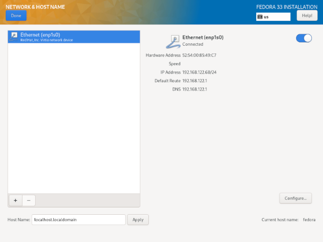
本地访问接口会被安装程序自动检测,且不能被手动添加或删除。所有检测到的接口都在屏幕左侧被列表列出来。点击列表中的一个接口可以显示该接口当前的配置(例如IP和DNS地址),此时接口的详细信息会在屏幕右侧被显示出来。
在接口列表的下方有两个按钮。点击“+”按钮可以添加一个虚拟网络接口(例如Team、Bond或者VLAN),这类接口的信息详见添加一个虚拟网络接口。要删除之前已有的虚拟网络接口,你需要在列表中选中此接口,然后点击“-”按钮。
要修改已有虚拟接口或者物理接口的设置(例如IP地址、DNS服务器或者路由配置),你需要在左侧面板选择要修改的接口,然后点击屏幕右下角的“配置”按钮。可用的设置详见编辑网络接口配置。
点击屏幕右上角的`ON`/`OFF`按钮可以启用或禁用当前选择的接口。
在连接列表下方,你可以在“主机名”输入框内输入这台电脑的主机名。主机名既可以是一个格式为_hostname_.domainname_的_完全限定域名 (FQDN),也可以是一个短格式的、不带域名的主机名。很多网络都有一个_动态主机配置协议_ (DHCP)服务,用于自动分配连接的操作系统的域名。要想允许DHCP服务为本机分配域名,则必须指定短格式主机名。
添加一个虚拟网络接口
要增加一个虚拟网络接口,你需要点击在接口列表底部的“+”按钮。一个新的窗口将打开,提示你需要从三种可用虚拟接口类型当中来选择一种:
-
“Bond”——NIC (网络接口控制器)连接,是一种连接多个物理网络接口到一个连接的通道上的方法。
-
“Team”——NIC网卡聚合,是一种新引入的聚合链接,它被设计用于提供一个小的内核驱动来引入数据包流的快速处理,并且提供大量应用在用户空间里做其他所有的事情。
-
“Vlan”(虚拟局域网)——一种创建多个不同的、相互隔离的广播域名的方法。
选择你想要添加的类型,然后点击“Add”按钮。另一个对话框将弹出,它允许你编辑选定的接口类型的所有可用的设置。更多可用设置的信息详见[citetitle]Fedora 网络 指南, available at https://docs.fedoraproject.org/的各个章节。基本文档也可以通过编辑网络接口配置获取到。
|
在关闭设置对话框后,如果你想再次访问这个对话框,就需要在配置接口的列表中选择相同的接口,然后点击屏幕右下角的“配置”按钮。如果你想移除一个虚拟接口,那你需要在列表当中选中要移除的接口,然后点击下方的“-”按钮。 |
编辑网络接口配置
本节仅详细介绍安装期间有线连接所需要的一些最重要的设置。在大多数安装方案中,许多可用配置不必更改,也不会保留到已安装的系统中。其他类型网络的配置大体相似,但具体配置参数可能不同。 要了解有关安装后网络配置的更多信息,请参阅 Fedora Networking Guide 的 Fedora Networking Guide。
To configure a network connection manually, select that connection in the list on the left side of the screen, and click the Configure button. A dialog will appear that allows you to configure the selected connection. The configuration options presented depends on the connection type - the available options will be slightly different depending on whether it is a physical interface (wired or wireless network interface controller) or a virtual interface (Bond, Team or Vlan) which you previously configured in Adding a Virtual Network Interface.. A full description of all configuration settings for all connection types is beyond the scope of this document; see the Networking Guide for details.
The most common and useful options in the configuration dialog are:
- Enable or disable the connection by default
-
In the
Generaltab of the configuration dialog, you can select or unselect theAutomatically connect to this network when it is availablecheck box to allow or disallow this connection to connect by default. When enabled on a wired connection, this means the system will typically connect during startup (unless you unplug the network cable); on a wireless connection, it means that the interface will attempt to connect to any known wireless networks in range.Additionally, you can allow or disallow all users on the system from connecting to this network using the
All users may connect to this networkoption. If you disable this option, onlyrootwill be able to connect to this network.It is not possible to only allow a specific user other than
rootto use this interface, because no other users are created at this point during the installation. If you need a connection for a different user, you must configure it after the installation. - Set up static IPv4 or IPv6 settings
-
By default, both
IPv4andIPv6are set to automatic configuration depending on current network settings. This means that addresses such as the local IP address, DNS address, and other settings will be detected automatically each time the interface connects to a network. In many cases, this is sufficient, but you can also provide static configuration in theIPv4 SettingsandIPv6 Settings, respectively.To set static network configuration, navigate to one of the settings tabs and select a method other than
Automatic(for example,Manual) from theMethoddrop-down menu. This will enable theAddressesfield below.In the
IPv6 Settingstab, you can also set the method toIgnoreto disableIPv6on this interface.Then, click
Addon the right side and add a set of settings:Address,Netmask(forIPv4),Prefix(forIPv6), andGateway.The
DNS serversfield accepts one or more IP addresses of DNS servers - for example,10.0.0.1,10.0.0.8.The final option in both tabs is
Require IPvX addressing for this connection to complete. Select this option in theIPv4tab to only allow this connection ifIPv4was successful; the same principle applies to this setting in theIPv6tab. If this option remains disabled for bothIPv4andIPv6, the interface will be able to connect if configuration succeeds on either IP protocol. - Configure routes
-
In the
IPv4 SettingsandIPv4 Settingstabs, click theRoutesbutton in the bottom right corner to configure routing settings for a specific IP protocol on an interface. A new dialog will open, allowing you toAdda specific route.If you confire at least one static route, you can disallow all routes not specifically configured here by enabling the
Ignore automatically obtained routes.Select
Use this connection only for resources on its networkto prevent this connection from becoming the default route. This option can be selected even if you did not configure any static routes. Enabling this option means that this route will only be used when necessary to access certain resources, such as intranet pages which require a local or VPN connection. Another (default) route will be used for publicly available resources if possible. Note that unlike the additional routes configured in this dialog, this setting will be transferred to the installed system. Also note that this option is only useful when more than one interface is configured.When you finish configuring the interface’s routing settings, click
OKto return to the configuration dialog.
Once you finish configuring the interface, click Save in the configuration window’s bottom right corner to save your settings and return to Network & Hostname.
Root Password
The Root Password screen is used to configure the root password for your system. This password will be used to log into the administrator (also known as superuser) account, which is used for system administration tasks such as installing and updating software packages and changing system-wide configuration such as network and firewall settings, storage options and adding or modifying users, groups and file permissions.
The root account will always be created during the installation. However, you should always also create a normal user account in Create User and use that account to log in to the system. Only switch to the administrator account only when you need to perform a task which requires administrator access.
|
The |

Once you choose a strong password, enter it in the Root Password field. The characters you write will be displayed as dots for security. Then, type the same password into the Confirm field to ensure you entered it properly. Both entered passwords must be the same.
As you enter the password, it will be evaluated and the installer will determine the password’s strength. If the installer considers your password weak, a message will appear at the bottom of the screen, explaining which aspect of your chosen password is considered insuficient. For example:
The password you have provided is weak:The password is shorter than 5 characters.
If a message similar to the above appears, it is highly recommended to choose a different, stronger password.
Once you configure the superuser password, click Done in the top left corner to return to Configuration and Installation Progress. If you selected a weak password, you must press the button twice.
Create User
The Create User screen can be used to create and configure one normal (non-root) user account during the installation. Only one user account can be configured here; if you require more accounts, wait until the installation completes, reboot your system and then create other accounts using either the useradd command in a terminal, or a graphical utility for managing user accounts (for example, the Users screen in the Settings menu in GNOME).
|
Creating a normal user account is not required to finish the installation; however, it is highly recommended. If you do not create one, you will have to log in to the system as |
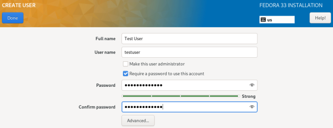
To configure a user account, fill out the Full name (for example, John Smith) and Username (for example, jsmith). The username will used to log in from a command line; if you install a graphical environment, then your graphical login manager will use Full name.
Make sure that the Require a password to use this account check box is enabled, enter a password you want to use for this account into the Password field. The characters you write will be displayed as dots for security. Then, repeat the same password in the Confirm password field below to ensure you entered it properly. Both entered passwords must be the same.
As you enter the password, it will be evaluated and the installer will determine the password’s strength. If the installer considers your password weak, a message will appear at the bottom of the screen, explaining which aspect of your chosen password is considered insuficient. For example:
The password you have provided is weak:The password is shorter than 5 characters.
If a message similar to the above appears, it is highly recommended to choose a different, stronger password.
The Make this user administrator check box gives the user you are creatng administrative rights (by adding this user into the wheel group), allowing this user to use the sudo command to perform tasks normally only available to root using only the user password, instead of the root password. This may be more convenient, but can also pose a security risk.
|
If you give administrator privileges to an user, make sure that the account is protected by a strong password. Never give an user administrator privileges without requiring any password for the account. See the Fedora Security Guide, available at the https://docs.fedoraproject.org/, for detailed information about password security including guidelines for selecting strong passwords. |
To additional settings, click the Advanced button below the password input fields. A new dialog window titled Advanced User Configuration will open. This dialog is described in the following section.
Advanced User Configuration
The Advanced User Configuration dialog allows you to change the following settings for the new user account.
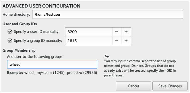
-
The user’s
Home directory(/home/usernameby default). -
The user’s ID (UID). The default value is 1000. UIDs 0-999 are reserved by the system so they cannot be assigned to an user.
-
The the group ID (GID) of the user’s default group. The default group name will be the same as the user name, and its default GID is 1000. GIDs 0-999 are reserved by the system so they cannot be assigned to an user’s group.
-
The user’s group membership. The user account you are creating will always have one default group membership (the user’s default group with an ID set in the
Specify a group ID manuallyfield). In theGroup Membershipfield, you can specify additional groups as a comma-separated list. Groups which do not already exist will be created; you can specify custom GIDs for them in parentheses. If you do not specify a custom GID for a new group, it will be assigned automatically.
Installation Progress
The Installation Progress screen is displayed after you finish configuring all required items in Installation Summary and press the Begin installation button. After this point, the installation process actually starts and changes are being made to your selected disks. It is not possible to go back to the Installation Summary and change any settings configured there; if you need to do so, you must wait for the installation process to finish, reboot your system, log in and change your settings on the installed system.
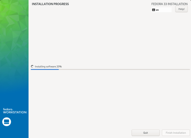
The bottom of the screen shows a progress bar and a message informing you of the current progress of the installation. When the installation finishes and the root password has been set, you can press the Finish installation button to reboot your computer and log in to your newly installed Fedora system.
|
Before you finish the installation and reboot, either remove the media (CD, DVD or a USB drive) which you used to start the installation, or make sure that your system tries to boot from the hard drive before trying removable media. Otherwise, your computer will start the installer again instead of the installed system. |
Want to help? Learn how to contribute to Fedora Docs ›